Basic HTML Version


3
IBRACON Structures and Materials Journal • 2012 • vol. 5 • nº 1
A. D. de Figueiredo | A. de la Fuente | A. Aguado | C. Molins | P. J. Chama Neto
assessment. This solution was chosen because it was prov-
en that there is no influence of number of cycles used in the
test on the response of FRCP [6 and 7]. Devices were fixed
to specimens providing a continuous acquisition of diametral
displacement in order to improve the verification of pipes me-
chanical behavior during the tests. A similar test set up was
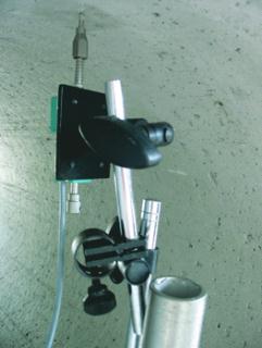
used in previous studies [8 and 9]. This system consists of
using LVDTs positioned against the upper part of the inner
surface of the pipe and attached at supports fixed at the bot-
tom part of the pipe as shown in Figures [2] and [3]. The set
up used for LVDTs positioning allows the measurement of di-
ametral displacements of the pipes without any interference of
external strains or dislocations in the results.
This paper presents an experimental program broader than previ-
ously published by the same authors [10]. Two test configurations
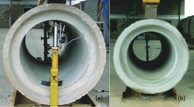
were used to measure the diametrical displacement of the pipes.
At first one, the measurement of displacement occurred simulta-
neously at the spigot and the socket, corresponding to positions
A and B (Figures [1] and [2a]). So, that situation turns possible to
obtain the curve of load by average diametrical displacement of
the pipes. In the second test configuration, only one LVDT was
placed at position A, corresponding to the spigot of the pipe (Fig-
ures [1] and [2b]). Thus, two series of pipes were produced with
fiber and conventional reinforcement to be tested with each of
those test configurations.
Each series was produced in a single day in order to diminish the
influence of intervening variables in the pipes production. In that
sense, the same features and basic materials that were being
regularly used by the company were applied for the pipes fabri-
cation. The demanded amount of fiber was added directly on the
aggregates conveyor belt. The rebars set up used is the same that
had been routinely used by the factory (Figure [4]). Three levels of
steel fibers consumptions (10 kg/m
3
, 20 kg/m
3
and 40 kg/m
3
) were
produced in each series together with three other SBRCP, totaling
24 pipes per series.
Figure 2 – Configurations adopted for the measurement of displacements
st
nd
(A) at both extremities in the 1 Series and (B) at the spigot for the 2 Series
A
B
Figure 3 – LVDT positioned at the upper part
of the inner surface of the pipe