Basic HTML Version


2
IBRACON Structures and Materials Journal • 2012 • vol. 5 • nº 1
Steel fiber reinforced concrete pipes. Part 1: technological analysis of the mechanical behavior
1. Introduction
There is a huge necessity for sewage collecting and treatment sys-
tems in underdevelopment countries. The concrete pipes can be con-
sidered as a very competitive and sustainable alternative in relation to
competitors in the market (Viñolas
et al.
[1]). Brazil has an instrument
to reduce the deficiency in this segment since publication of the stan-
dard ABNT NBR 8890 [2] that allow the use of steel fibers for concrete
pipes reinforcement [3]. This standard is equivalent to the European
norm NBN-EM 1916 [4]. Both standards allow the use of conventional
reinforcement with steel bars also. The pipes must to be verified in
terms of mechanical performance through the crushing test or three-
edge bearing test, despite the type of reinforcement used (bars of
fibers). However, the steel fibers reinforced concrete pipes (FRCP)
are not regularly used in Brazil nowadays, although the Brazilian stan-
dard had been published in 2007. One of the main reasons for this
situation is related to the doubts concerning the FRCP mechanical
performance that still remain in the market segment. These difficul-
ties are also associated with the lack of numerical models capable
of predicting the behavior of the component accurately. In order to
resolve these problems, an experimental study focusing on the be-
havioral assessment of concrete sewage pipes was carried out. This
study compared the performance between the pipes reinforced with
steel fibers (FRCP) and the pipes reinforced with cold drown steel
bars. The results turn possible the comparative performance evalua-
tion of FRCP and the steel bars reinforced concrete pipes (SBRCP),
and also the validation of a proposed numerical model for prediction
of the pipe behavior during the crushing strength (de la Fuente et al.
[5]). In this study, the influence of changes in testing methodology in
the response of the components was also evaluated.
2. Methodology
The mechanical performance of concrete pipes is regularly mea-
sured with the crushing test method as specified by the standards
ABNT NBR 8890 [2] and EN 1916 [4] (Figure [1]). These standards
prescribe two different procedures for the qualification of pipes,
one for SBRCP, and the other for FRCP.
In the case of SBRCP, the pipe is subjected to a continuous
loading up to rupture in order to determine the proof and ulti-
mate loads. The proof load (
F
c
) is defined as 0.67
F
n
, and
F
n
is
the minimum crushing load. The strength class is defined by the
F
c
, and is acceptable to be equal to the crack load (
F
cr
), corre-
sponding to a crack with an opening of 0.25 mm [2] or less than
0.3 mm [4] and length of 300 mm or more according to Brazilian
[2] and European [4] standards, respectively. The ultimate load
(
F
u
) is the maximum achieved during testing and shall be equal
or greater than
F
n
.
In the standard crushing test method for FRCP there is a cyclic
loading [2 and 4]. The first cycle consists of loading the pipe
until an equivalent level of the proof load of the SBRCP. At this
moment, the load is maintained for one minute and the pipe
is checked for evidence of any damage. The pipe is rejected
if any crack or other damage is observed. Thus, it is required
that
F
cr
shall be greater
F
c
. Once approved at this stage, the
loading of the pipe is continued until the maximum load (
F
u
).
When the load start to decrease and reach the value of 95% of
F
u
it shall be release, finishing the first cycle of the test. On the
second cycle of the test, the pipe is reloaded up to
F
c
and held
for one minute. The pipe has to withstand this post-peak proof
load in order to be approved. The test procedure established
by the European standard [4] is finished at this point. In the
specific case of the Brazilian standard [2], the second cycle
is continued increasing the loading up to the moment that the
pipe reach the maximum measured post-peak load (
F
max,pos
).
The
F
max,pos
shall be greater than 1.05
F
c
, named minimum re-
quired post-peak load (
F
min,pos
).
Although there are different test procedures prescribed by the
standards to verify pipes with varied types of reinforcement,
the continuous test was used in this experimental program in
order to evaluate all specimens under uniform conditions of
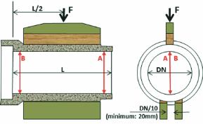
Figure 1 – Front and side views of the configuration adopted
for the crushing test of concrete pipes