Basic HTML Version


260
IBRACON Structures and Materials Journal • 2012 • vol. 5 • nº 2
Three-dimensional analysis of two-pile caps
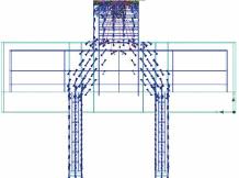
propagated up to piles surfaces, forming compressive struts and
concentrating at the piles cross-section closest to the column, as
shown in Figures 8 and 9.
Maximum compressive stresses, presented in Table 8, occurred in
the intersection between column-pile cap and piles-pile cap. This
indicates the collapse of pile caps in the nodal zones region, simi-
larly to [1] specimen rupture.
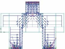
In models 2 and 3, the eccentricity provoked by piles supports area
reduction, which resulted in an augment in structure’s displacement,
caused struts stress expansion towards the inferior nodal zone. This
resulted in a redistribution of pile cap stresses at the piles surface.
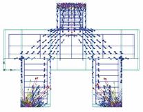
In model 3, struts stress flow became to concentrate in the pile’s
surface that is closer to the pile caps border, as shown in Figure 9 (b)
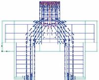
In model 5, presented in Figure 9 (d), struts compressive stresses
were distributed in all piles cross-section area. Notwithstanding,
maximum stresses were similar in value to model 1, as shown in
Table 8, proving that in model 1 piles cross-section surfaces were
only partially solicited by struts compressive stresses.
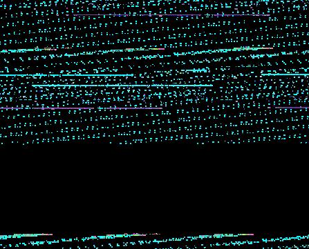
Tensile stresses perpendicular to compressive struts were also
formed, characterizing concrete splitting, which is indicated by ten-
sile vectors perpendicular to compressive vectors shown in details
in Figure 8. Splitting steel bars of model 4 absorbed partially these
tensile stresses, contributing to pile caps resistance increase, as
predicted by Delalibera [1]. A significant reduction in tensile stress
was also observed on the pile cap’s inferior surface (between piles)
as shown in Figure 12 (a). These results confirm splitting steel bars
favorable action to pile caps tensile and shear resistance increase.
In the other models, tensile stress in the pile cap inferior surface
was similar, as shown in Figures 10, 11 and 12 (a and b).
4.3 Ultimate load and ruin
In all models a fragile collapse occurred with compressive struts
formation and concrete splitting and crushing. Also intensive
cracks were observed.
Ultimate load in model 1 was 1900 kN. Comparing to the experi-
mental model the results were very similar, as demonstrated in
Table 9.
In model 3, with supports in only 25% of the pile’s basis, the princi-
pal reinforcing bars of the ties yielded. There was also a reduction
in pile cap load carrying capacity. In the other models, yielding oc-
curred only after the model’s ruin.
In model 4, with splitting reinforcing bars, an increase in pile cap ulti-
mate load capacity was observed, as shown in Table 9. In addition,
no significant variation was observed in pile cap’s ruin, stiffness and
bearing capacity patterns. The numerical results are similar to those
obtained by [1] in experimental tests with pile caps with splitting rein-
forcement where an augment in pile cap’s ultimate load was obtained.
In model 5, despite piles cross-section area reduction, no signifi-
cant difference was observed in pile cap bearing capacity. Ulti-
mate load capacity of the numerical model was 1825 kN, which is
close to the experimental model. The results restate that piles of
numerical model 1 are only partially solicited, occurring compres-
sive stress concentration in the pile’s cross-section area that are
closer to the column (in the beginning of the inferior nodal zone).
4.4 Reinforcement strains and stresses
Steel bars, except in model 3, did not yield until the pile caps
ruin. Moreover, the ties steel bar stresses were not uniform,
Figure 8 – Principal stress flow of model 1,
highlighting tensile stresses activity (ATENA)
Figure 9 – Principal stress flow - (a) model 2; (b) model 3; (c) model 4; (d) model 5 (ATENA)
(a)
(b)
(c)
(d)