Basic HTML Version


258
IBRACON Structures and Materials Journal • 2012 • vol. 5 • nº 2
Three-dimensional analysis of two-pile caps
In model 5, with reduction of pile’s cross-section area, the results
were very similar to those observed in model 1.
In general, a good approximation between experimental and nu-
merical results was observed, as it can be verified in the results
presented in Table 7.
4.2 Stress-flow
In all numerical models prismatic compressive struts were
formed. At the bottom surface of the column stress flow was di-
vided equally in two halves, proving [1] statement that it is cor-
rect to consider that half pile cap-column interface receives half
of the column’s forces. Besides, all compressive stresses have
Figure 3 – Details of piles reinforcement bars– (a) models 1, 2, 3 e 4; (b) model 5
(a)
(b)
Figure 4 – Details of column's
reinforcement bars
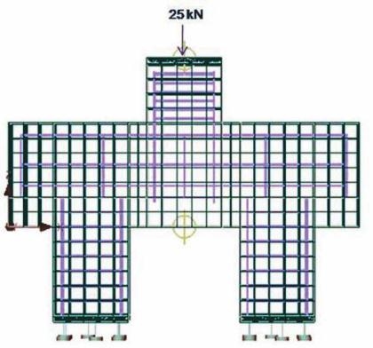
Figure 5 – Details of finite element mesh,
piles support restraints and load. (ATENA)
Table 6 – Contact elements properties
Normal Stiffness (K )
nn
5
3
2,0 . 10 kN/m
Tangential Stiffness (K )
tt
5
3
2,0 . 10 kN/m
Cohesion
0,0
Friction Coefficient
0,0
Ultimate Concrete
Tensile Strength (f )
tk
3,2 MPa