Basic HTML Version


15
IBRACON Structures and Materials Journal • 2012 • vol. 5 • nº 1
A. D. de Figueiredo | A. de la Fuente | A. Aguado | C. Molins | P. J. Chama Neto
ture
χ
bymeans of the length of the hinge
l
bc
throughEq. 2 (seePedersen
[30]). The value of
l
bc
varies depending on the stress level of the section;
however, some authors (Pedersen [30] and Olesen [31]) establish it as
a constant value of
h
/2, and still others (Casanova [32]) propose that it
should vary depending on the crack height (
s
n
). For this paper, a con-
stant value of
h
/2 for
l
bc
has been adopted, following the recommenda-
tions proposed by Pedersen [30] for the analysis of FRCP.
(1)
w = s
n
tan φ
(2)
φ = l
bc
χ
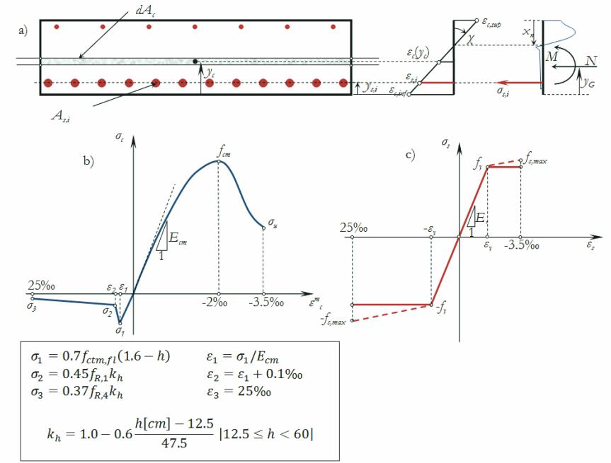
The steel rebars are modeled with a trilineal diagram, with the
possibility of simulate the hardening response of the material (see
Figure [3c]).
The value of the crack width (
w
) is calculated considering that the crack
surfaces rotate as a rigid body (see Figure [4]), forming a
φ
angle be-
tween the crack faces (Eq. 1). This angle is related to the sectional curva-
Figure 3 – (a) Cross section discretization, (b) Compression and tensile SFRC laws
and (c) constitutive diagram adopted to simulate the passive steel behavior
Figure 4 – Rigid body schema adopted
to assess w
φ
w
h
s
n
σ
c
(
ε
c
)
Non linear regime
Linear regime
Linear regime
l
bc
=
h
/2