Basic HTML Version


1. Introduction
Unreinforced concrete pipes (UCP) and steel bar reinforced con-
crete pipes (SBRCP) are well-known and accepted solutions for
drainage and sewage pipes (Viñolas
et al
. [1]).
On the other hand, fibre reinforced concrete pipes (FRCP) and
those reinforced with steel rebars and fibres (SBFRCP) are other
underdevelopment alternatives (Haktanir
et al
. [2], de la Fuente
et
al
. [3 and 4], Figuereido [5], Figueiredo
et al
. [6] and Lambrechts
[7]). In this respect, the addition of fibres provides advantages from
both the technical and the economic point of view. From the techni-
cal point of view, a substantial improvement of several mechanical
properties of concrete is achieved (As’ad
et al
. [8]), especially with
the addition of metallic fibres (Blanco [9]). Likewise, the compos-
ite solution leads to a positive structural synergy: the steel rebars
perform the main strength function (Chiaia
et al
. [10]), whereas
the fibres bridge the cracks, reducing their average spacing and
width. The fibres also contribute to the strength function (Blanco
et
al
. [11]). The use of fibres also contribute economically, because
allows saving up on the assembling operations related to conven-
tional reinforcement, reducing labor force, equipment use, and as-
sociated risks (de la Fuente et al. [12]).
FRCP and SBFRCP have already been considered as alterna-
tives for UCP and SBRCP in several experimental campaigns
both in Brazil (see Figueiredo
et al
. [6 and 13]) and Spain (see
de la Fuente
et al
. [3]). However, their introduction in the mar-
ket is under progress due to several factors such as: (1) the risk
of damage when FRCP are manipulated; (2) the lack of calcu-
lation methods for this type of material, and (3) the difficulty to
overcome the inertia towards change (Parrot [14]). Nonetheless,
nowadays there are solutions for such problems: (1) polishing
with emery powder in order to remove imperfections and avoid
possible injuries; (2) constitutive equations to consider the tensile
behavior of the steel fibre reinforced concrete (SFRC) (Hillerborg
et al
. [15], Vandewalle
et al
. [16] and Laranjeira
et al
. [17]), and
(3) it has been verified that the incorporation of fibres improves
the response of the pipe and leads to a global reduction of costs
(Pedersen 1992 [18]).
Another relevant aspect related to FRCP and SBFRCP technology
is the lack of recommendations and simplified calculation methods.
Because of this, the design of FRCP and SBFRCP is normally car-
ried out by trial and error: trying out several dosages and/or con-
crete thickness until finding an optimal amount of fibres that meet
the requirements of the desired strength class in the crushing test
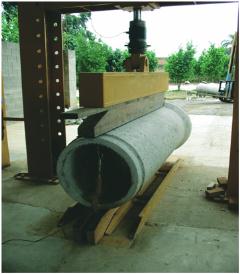
(CT) (Figure [1]). This design procedure is hardly operative, uneco-
nomical and inefficient due to the variety of diameters, thickness,
strength classes, types of fibres and the factory limitations. For this
reason, it is necessary to develop analytical and/or numerical tools
that would make possible to carry out the optimal design and the
verification of concrete pipes (CP), especially FRCP and SBFRCP,
in order to avoid the regular procedures traditionally used.
The aim of this paper is, firstly, to introduce a model for the non-
linear analysis of CP of medium-small diameter (less than 1000
mm) called Mechanical Analysis of Pipes (MAP) which is able to
simulate the CT; and, secondly, to contrast the numerical and the
experimental results in order to achieve the model validation.
Initially, a summarized exposition of the normalized CT procedure
is presented. Then, the bases considered in the MAP model are
mentioned, and the model results are contrasted with the results
presented in the first part of this work (Figueiredo
et al
. [19]). Fi-
nally, an example of the application of MAP is presented aiming at
determining the optimal amount of fibres for a pipe with 400 mm
of
D
i
.
2. Crushing Test
The NBR 8890:2007 [20] specifies the procedures and all the de-
tails that should be observed during the execution of the CT. Both
the cross and the longitudinal sections of the test configuration are
schematically shown in Figure [2].
The load process and the strength requirements are function of the
type of reinforcement. In the case of steel fibre reinforced concrete
pipes (SFRCP) the requirements are presented below:
1. Withstand the proof load (
F
c
) during a minute without cracking
or, in other words, without exceeding the first cracking load
(
F
cr
).
F
c
is equivalent to the 67% of the minimum failure load (
F
n
).
2. Reach the ultimate failure load
F
u
, which must be higher than
F
n
.
3. When the load has decreased a 5% of
F
u
, or more, the pipe is
completely downloaded and reloaded until reaching
F
c
. This
load level must be supported for more than a minute.
4. The loading process must continue until reaching a minimum
post failure load (
F
min,pos
) equivalent to, at least, 105% of
F
c
.
The purpose of this cyclic loading process is to verify if the type
and amount of fibres are the suitable ones to guarantee the
F
min,pos
load and, indirectly, if the fibre-concrete anchorage and the post-
peak strength of SFRC are appropriate (Figueiredo [5]).
A. D. de Figueiredo | A. de la Fuente | A. Aguado | C. Molins | P. J. Chama Neto
Figure 1 – Three edge bearing test
or crushing test
13
IBRACON Structures and Materials Journal • 2012 • vol. 5 • nº 1